Contents

Robotic Projects for Kids: While most of us are intrigued by multi-functioning robots, the question about how these incredible humanoids are built crosses our minds quite often. The inquisitive ones among us are curious about how to get started with learning more about robotics and also building a robot of their own. Hi-technology and robotics may seem overwhelming to us, but there are interesting ways to dip your toes into the world of robotics before completely diving into it.
And to help you with it here is a detailed article, which helps children to build their robots. With the help of DIY robotic projects provided on this page, children can easily start building robots on their own. Scroll down to learn more about robotic ideas.
Looking to learn Robotics? Explore Wiingy’s Online Robotics Classes For Kids to learn from top Robotics experts.
Things Required To Build Robots at Home
To get started with the DIY robotic projects, you will need the following components.
- 2 Red LEDs
- 2 Green LEDs
- 2 Yellow LEDs
- Breadbox
- Battery Case
- Buzzer
- 3 IR Sensors
- Colorful Jumper Wire
You can easily buy these components from an electronic store or online. You can also get these components together in the Wiingy Starter Kit as well.
Basic Components of a Robot and Their Functions
The basic components of a Robot and their functions are explained below:
LED
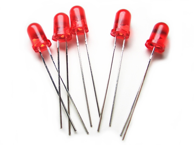
You’ve probably noticed LEDs in a variety of places around you, such as decorative lights at a festival, red and green status lights in electronic devices, and so on.
LEDs: LED stands for the light-emitting diode. LED works on a very simple principle, it has two pins, one positive and one negative.
But how to identify them?
There is a very easy way to remember this: the longer pin is the positive pin, and the shorter one is negative. How it works is that when we connect the positive and negative terminal of the battery with the positive and negative terminal of the LED, respectively, we see that the LED lights up.
Buzzer
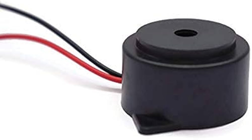
Let’s talk about buzzers now. A buzzer is a device that produces a buzzing sound when it is powered. You must have seen the participants tapping the buzzer in reality shows. Similar to LED lights, this buzzer consists of two pins, one positive and one negative. When it’s connected to a battery, it produces its intended output, i.e., a buzzing sound.
This is how it looks in reality.
Jumper Wires
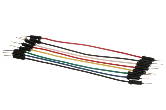
Now let’s move to jumper wires.
You can observe that in the picture above, in one bundle, all the wires have pins on both sides, while in the other bundle, the wires have pins only on one side. If pins are on both sides, it is called “male-to-male jumper wires.” If pins are only on one side, they are called male-to-female jumper wires.
Breadboard
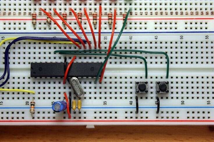
You need a breadboard to get started with even the simplest robotics project. A breadboard is a simple device that allows us to create circuits without the need for soldering. You can see the grid-like structure on the breadboard. Each hole on the breadboard can be labeled. Let’s understand how to do that.
You can see the labels a, b, c, d, e, f written along these rows, and similarly 1, 2, 3, and up to 30 are written in these columns.
Let’s consider this hole. Check the label corresponding to this row, i.e., C and column 15, so the name of this hole is C15.
Breadboards have long lines at the sides; one is negative and the other is positive. As shown in the diagram, they are all connected among themselves.
Battery Case
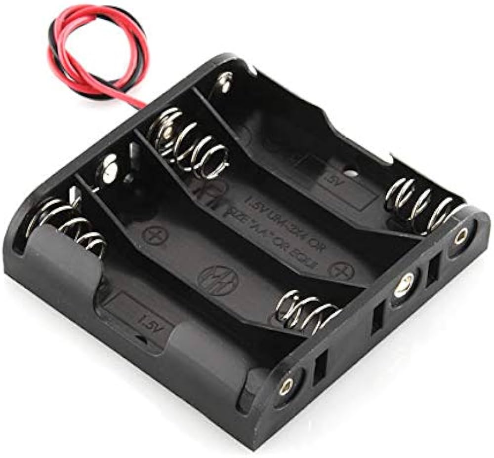
The battery case will have 4 slots where you have to add 4 AA batteries. It also has two wires. The red one is the positive terminal, and the black one is the negative terminal. There is a switch, which you can use to turn on or off the power coming from the battery.
IR Sensors
Finally, we have the most interesting part used in robotics projects, the IR sensors. IR stands for Infrared. It works on the principle of reflection of IR light. You must have seen automatic water taps, where when you put your hand in front of it, the water comes out. That is an example of where IR sensors are used.
The sensor consists of the following:
- VCC, Ground, and Out Pins
- Transmitter
- Receiver
Let’s understand the VCC & GND pins of the IR sensor first.
- The VCC pin will act as the positive pin of the sensor.
- And the GND pin will be the negative pin of the sensor, just like LEDs have positive and negative terminals.
- The OUT pin is known as the control pin, which signals the control system whether the object is present in front of the sensor or not. “
The white LED is known as a transmitter, and it transmits IR light. The black LED is known as the receiver. It receives the IR light. Suppose, if the object is present in front of the sensor, then the IR light coming from the transmitter will get reflected and the receiver will receive it and give a signal to the control unit through the OUT pin.
With these powerful components, you can jump right into creating your own robots. Let’s dive right into it!
Robotic Project 1: Smart Street Light
As the name suggests, smart street lights are those street lights that automatically turn on and off, depending upon the car’s presence or absence. Smart Streets save energy consumption as traditional street lights remain turned on, even when they aren’t required. This causes unnecessary electricity wastage. On the other hand, Smart Street Lights, on the other hand, sense the presence of any person or car in front of them and then get switched on, which significantly reduces the wastage of energy.
So let’s dive into how to build your very own smart street light. The components you will need for this project are:
- Two LED lights
- Male to Female Jumper Wires
- Two IR sensors
- Breadboard
- Battery case
Additionally, you will also require four AA batteries.
We will learn how to create a smart street light circuit in eight simple steps:
Step 1: Plug the Led Into the Breadboard
In this step, the LED will be connected to the breadboard. The longer leg of the LED is the positive terminal, and the shorter leg is the negative terminal. You can connect the negative terminal of the LED to any cell in the grid. For example, connect it to d26.
We then proceed to connect the positive terminal of the LED to the positive rail of the breadboard. You can connect it anywhere on the positive rail.
Step 2: We Will Repeat the Previous Step for Led No.2
As a step 2, we will repeat the step for LED no.2. Let’s connect this LED’s negative terminal to d5 and its positive terminal to the corresponding cell in the positive rail.
Step 3: Install the VCC-off Sensor
Now, we will connect the IR sensor with the jumper wires.
Connect the female part of the jumper wires with the three pins on the IR Sensor. As you remember, it has three pins; VCC, VCC, Ground, and an Out pin.
Step 4: Connect the First Pin of the IR Sensor to the Circuit.
Let’s connect the VCC of the IR Sensor to the positive rail of the breadboard using a male-to-female jumper wire. Note that you can choose any of the cells present in the corresponding rows because all of them are connected.
Step 5: Connect the Sensor’s Ground
Connect the ground to any cell in the negative row of the breadboard. A quick tip here: these connections are very important, so connect very carefully. Connecting the wrong wire to the positive and negative can immediately lead to the sensor’s failure.
Step 6: Connect the Sensor’s Outpin to the LED’s Negative.
The out pin of the sensor will be connected to the negative terminal of the LED. We are connecting it to cell c5.
Understand the Logic:
Let’s understand why we are doing so.
If any object is present in front of the sensor, the IR sensor gives an OV output at the output, which completes the circuit, and the output LED glows. When there is no object present, the out pin is at 5V and the circuit isn’t complete, which causes the LEDs to turn off. This is the primary logic flow, so make sure you understand it very carefully.
Step 7: Attach the Battery
Now to power the overall circuit, we will connect the battery to the circuit. But before making the connection, Let’s put the 4 AA batteries into the case first. Don’t forget to close the lid of the case.
Step 8: Final Results
You can see that two status lights are now on in the IR sensors. This means they are working fine.
Now the circuit is ready. As we move our hand in front of the IR sensors, the led lights up, and when the hands are away, it is off.
Robotic Project 2: Touchless Bell
At COVID times, we have realized the importance of hygiene and that harmful diseases are being transferred from surfaces. This has created a need for touchless devices. Touchless devices are being used all over the place, be it automatic sanitizer dispensers, touchless taps, etc. Today we will be looking at how to build a touchless doorbell. Your guest will not have to press the button; they can just wave their hand in front of the sensor and the bell will ring.
The basic components required for this project are
- Buzzer,
- Jumper Cables
- Infrared Sensors
- Breadboard
- Battery Carrying Case
We will also need four AA batteries. We will learn how to conduct this project in just six simple steps. This is the circuit which will be the final output. Let’s start building it!
Step 1: Connect the Buzzer To the Breadboard
As a first step, we will first connect the buzzer to the breadboard. Like with LEDs, the longer leg of the buzzer is the positive terminal and the shorter leg is the negative terminal. You can connect the negative terminal of the buzzer to any cell in the grid. For this project, we will connect it to A2, and the positive terminal to the positive rail of the breadboard.
Step 2: Use the Jumper Wires to Connect the IR Sensor
In this step, we will connect the IR sensor with the jumper wires.
Step 3: Connect the Vcc-Pin IR Sensor With the Positive Rail of the Breadboard
Coming to the IR Sensor, as you remember, it has three pins: VCC, Ground, and Out pin. Connect the VCC of the IR Sensor to the positive of the breadboard using a male to female jumper wire.
As discussed previously, you can choose any of the cells present in the corresponding rows because they are all connected.
Step 4: Connect the Ground Pin to the Circuit
In this step, we connect the ground pin to any cell in the negative row of the breadboard. Now it’s time for the most important step: connecting the out pin of the IR Sensors. Please make the connections carefully.
Let’s Understand Why We Are Doing So?
The logic is very simple: if any object is present in front of the sensor, the IR sensor gives an OV output at the outpin, which completes the circuit, and the output LED glows.
When there is no object present, the out pin is at 5V and the circuit isn’t complete, which causes the LEDs to turn off. This is the primary logic flow that is used in this project.
Step 5: Connect the Battery to the Circuit
So, connect the battery’s positive and negative terminals to the positive and negative terminals of the breadboard. But before making the connection, let’s put the four AA batteries into the case first. Don’t forget to close the lid of the case.
Step 6: Connecting Terminals
Finally, connect the battery’s positive and negative terminals to the positive and negative rails of the breadboard, respectively. When we switch it on, you will be able to see that small led lights are turned on in the IR sensors. This means it is working fine. As we move the objects in front of the IR Sensor, you’ll notice it produces a beep sound, and when it is far enough, the buzzer stops making the buzzing sound.
Applications of Touchless Bell
This concept is being used in touchless bells. You have to install the buzzer inside your home, most probably in the living room, where everybody can hear it. You will then have to install the sensor with the proper packaging adjacent to the door. Do label it properly.
When your guests arrive, they will just wave their hand outside the door, at the desired location, and the bell will ring.
Robotic Project 3: Object Detection System
Let us start by understanding what these object detection systems are.
As the name suggests, the detection system detects the presence of objects or obstacles in front of it and gives the signal back to us.
But why is it needed?
Automated vehicles or moving robots need a signal to understand their surroundings. So that they can perform the desired action after that. Complex systems, such as self-driving cars, use multiple sensors to understand their surroundings.
In this project, we will build a single-sensor object detection system and learn the basic concepts that are used in it. Let’s dive into the project, and learn the concepts behind it.
Components Required To Build Object Detection System
Let’s look at the components needed for the project:
- Two LED lights
- Jumper Wires from Male to Female
- Two infrared sensors
- Breadboard
- Battery container
We will also need four AA batteries.
Step 1: Attaching the Led to the Breadboard
Now let’s start the connection. As we remember, the longer leg of the LED is the positive terminal and the shorter leg is the negative terminal. You can connect the negative terminal of the LED to any cell in the grid. For this project, we will connect it to d26.
We will now connect the positive terminal of the LED to the positive rail of the breadboard. You can connect it anywhere on the positive rail.
Step 2: Connect the Led 2 to the Breadboard
Let’s connect this LED’s negative terminal to d5, and the positive terminal to the corresponding cell in the positive rail.
Step 3: Connect the IR Sensor with the Jumper Wires
We will now connect the IR sensor with the jumper wires.
Connect the female part of the jumper wires with the three pins on the IR Sensor.
As you remember from the previous video, it has three pins: VCC, Ground, and Out pin.
Step 4: Connect the VCC of the IR Sensor to the Positive Rail of the Breadboard
Let’s connect the VCC of the IR Sensor to the positive rail of the breadboard using a male-to-female jumper wire.
Note that you can choose any of the cells present in the corresponding rows because all of them are connected, as discussed in our first video.
Step 5: Connect the IR Sensors’ GND Pins
Connect the ground to any cell in the negative row of the breadboard.
A quick tip here: these connections are very important, so connect them very carefully. Connecting the wrong wire to the positive and negative can immediately lead to the sensor’s failure.
Step 6: Connect the IR Sensors’ Out Pins to the LED’s Negative Terminal
The out pin of the sensor will be connected to the negative terminal of the LED. For this project, we will connect it to cell c5.
Let Us Understand Why We Are Doing So?
The logic is very simple: if any object is present in front of the sensor, the IR sensor gives an OV output at the outpin, which completes the circuit, and the output LED glows.
When there is no object present, the out pin is at 5V and the circuit isn’t complete, which causes the LEDs to turn off. This is the primary logic flow, so make sure you grasp it.
Step 7: Connect the Other IR Sensor to the Circuit.
Now, similarly, in this step we will connect the second sensor to the second LED.
Step 8: Connect the Battery to the Circuit
Now, to power the overall circuit, we will connect the battery to the circuit. But before making the connection, we’ll put the four AA batteries into the case first. Don’t forget to close the lid of the case.
Final Result
You can see that two status lights are now on in the IR sensors. This means they are working fine. Now the circuit is ready. As we move our hand in front of the IR sensors, the led lights up, and when the hands are away, it is off.
Robotic Project 4: Blind Stick
Do you know that globally, there are 43 million people living with blindness and 295 million people living with moderate-to-severe visual impairment? Today we will try to solve one of their problems through this smart blind stick project.
You must have seen blind people struggling to move from one place to another. Their mobility is highly restricted due to the inability to see the obstacles in their way.
What if we could find a way to send them a signal whenever there is an obstacle in their path? This is what the whole blind stick project is all about.
Let’s now start building the project.
Components Required
The basic components required for this project are
- Buzzer,
- Jumper Cables
- Infrared Sensors
- Breadboard
- Battery Carrying Case
We will also need four AA batteries.
Step 1: Connect the Buzzer To the Breadboard
As a first step, we will first connect the buzzer to the breadboard.
Like with LEDs, the longer leg of the buzzer is the positive terminal and the shorter leg is the negative terminal. Now let’s start the connection.
You can connect the negative terminal of the buzzer to any cell in the grid. We are right now connecting it to A2 and the positive terminal to the positive rail of the breadboard.
Step 2: Use the Jumper Wires to Connect the IR Sensor
Now, we will connect the IR sensor with the jumper wires.
Step 3: Connect the VCC Pin of the IR Sensor With the Positive Rail of the Breadboard
Now comes the IR Sensor, as you remember, it has three pins, VCC, Ground, and Out pin. Connect the VCC of the IR Sensor to the positive of the breadboard using a male-to-female jumper wire. As shown in the diagram,
Note that you can choose any of the cells present in the corresponding rows because all of them are connected.
Step 4: Connect the GND Pin of the IR Sensor With the Negative Rail of the Breadboard
Step 4 is to connect the ground pin to the circuit. The ground can be connected to any cell in the negative row of the breadboard.
Step 5: Connect the Negative Terminal of the LED to the Out Pin IR Sensors
Now it’s time for the most important step: connecting the out pin of the IR Sensors.
The out pin of the sensor will be connected to the negative terminal of the buzzer. We are connecting it to cell c1. Make sure to make the connections carefully.
Let’s Understand Why We Are Doing So?
The logic is very simple: if any object is present in front of the sensor, the IR sensor gives an OV output at the outpin, which completes the circuit, and the output LED glows. When there is no object present, the out pin is at 5V and the circuit isn’t complete, which causes the LEDs to turn off. This is the primary logic flow that is used in this project.
Step 6: Connect the Battery to the Circuit
Connect the battery’s positive and negative terminals to the positive and negative terminals of the breadboard.
But before making the connection, let’s put the four AA batteries into the case first. Don’t forget to close the lid of the case.
Finally, connect the battery’s positive and negative terminals to the positive and negative rails of the breadboard, respectively. Let’s switch it on.
Final Results
You can see that small LED lights are turned on in the IR sensors. This means it is working fine.
As we move the objects in front of the IR Sensor, it produces a beep sound, and when it is far enough, the buzzer stops making the buzzing sound.
You can place this circuit on a stick, which the blind can use. So whenever there is an obstacle in their way, the buzzer will buzz, making them aware of the obstacle.
Robotic Project 5: Automated Home Alarm
It is very important to keep your home safe. But the question is how to do it? What if you could devise a system that gets the signal as the burglar enters your premises?
Smart home alarms can help you do this. It will produce a sound whenever someone enters your premises at night.
The basic components required for this project are
- Buzzer,
- Jumper Cables
- Infrared Sensors
- Breadboard
- Battery Carrying Case
We will also need four AA batteries.
We will learn how to conduct this project in just six simple steps. This is the circuit that will be the final output. Let’s start building it.
Step 1: Connect the Buzzer To the Breadboard
As a first step, we will first connect the buzzer to the breadboard.
Like with LEDs, the longer leg of the buzzer is the positive terminal and the shorter leg is the negative terminal. Now let’s start the connection.
You can connect the negative terminal of the buzzer to any cell in the grid. We are right now connecting it to A2, and a positive terminal to the positive rail of the breadboard.
Step 2: Use the Jumper Wires to Connect the IR Sensor
In this step, we will connect the IR sensor with the jumper wires.
Step 3: Connect the VCC Pin of the IR Sensor to the Breadboard’s Positive Rail
Now comes the IR Sensor. As you remember from the previous video, it has three pins; VCC, Ground, and Out pin. Connect the VCC of the IR Sensor to the positive of the breadboard using a male-to-female jumper wire.
As discussed previously, you can choose any of the cells present in the corresponding rows because they are all connected.
Step 4: Connect the Ground Pin IR Sensor With the Negative Rail of the Breadboard
Connect the Ground to any cell in the negative row of the breadboard.
Step 5: Connect the Outward-Pin IR Cell With the Negative Terminal of the LED
Now it’s time for the most important step: connecting the out pin of the IR Sensors.
The out pin of the sensor will be connected to the negative terminal of the buzzer. We are connecting it to cell c1. Please make the connections carefully.
Let’s Understand Why We Are Doing So?
The logic is very simple. If any object is present in front of the sensor, the IR sensor gives an OV output at the outpin, which completes the circuit, and the output LED glows.
When there is no object present, the out pin is at 5V and the circuit isn’t complete, which causes the LEDs to turn off. This is the primary logic flow that is used in this project.
Step 6: Connect the Battery to the Circuit
Now, to power the overall circuit, we will connect the battery to the circuit.
Connect the battery’s positive and negative terminals to the positive and negative terminals of the breadboard. But before making the connection, let’s put the 4 AA batteries into the case first. Don’t forget to close the lid of the case.
Looking to learn Robotics? Explore Wiingy’s Online Robotics Classes For Kids to learn from top Robotics experts.
Final Results
Finally, we will connect the battery’s positive and negative terminals to the positive and negative rails of the breadboard, respectively.
Let’s switch it on. You can see that small led lights are turned on in the IR sensors. This means it is working fine.
As you can see, as we move the objects in front of the IR Sensor, it produces a beep sound, and when it is far enough, the buzzer stops making the buzzing sound.
This is the concept that is being used in the burglar alarm system.
As you will be using this system at night, keep the buzzer, preferably in your bedroom. The location should be such that you can hear the voice coming from it when you are sleeping. You will have to place multiple sensors around the fence and key entry points of your house, such as doors and windows.
So, whenever at night someone enters your premises, the sensor will detect it, and the alarm will start ringing. This will wake you up, and then you can take the necessary action.
This will help you make your home safer. So, make your home safe right now by installing your own burglar alarm system.
With various tools, gadgets, and lots of creativity, you can build your own robot to help you out around the house. Believe it or not, robots are easy to build when you have the right guidance and tools to help you out.
For a beginner’s level guide to Robotics, read our Robotics for Kids blog.
Other Useful Reads
Coding For Kids | 10 Free Coding Websites To Get Started for Kids
Importance of Scratch Programming: 7 Benefits of Learning Scratch
Graphic Designing for Kids | 10 Beginner-Friendly Graphic Designing Tools
Best Extra-Curricular Activities for Kids